In our last Tech Talk, we covered controlling an RGB fixture with the SLESA. This week, we’re going to cover how to cut your fixture as well as how to install snap connectors!
Click here to jump to our Snap Connector assembly video.
Here are the tools and products we’re using today. From left to right we have
- RGB Snap Connector 02 End Exit kit
- Snap End Cap 01 kit
- Vivid RGB LED Neon Flex fixture
- Water-proof Grease (we’ll discuss this during the installation section)
- Plastic Inducer
- Anvil Cutter
Cutting LED Neon Flex
GLLS offers DIY end caps as well as leads with our Snap Connectors. This allows large runs of LED Neon Flex to be cut in the field. It is very important to know how to properly cut the fixture to prevent damage to the internal components, and to ensure a secure seal with the snap connectors.
The proper way to cut LED Neon Flex
This is an anvil cutter. To be able to cut LED Neon Flex correctly, you must use an anvil cutter or similar. The important thing when cutting a fixture is to have a clean, straight cut. Angled cuts will cause damage to the PCB, and prevent the snap connector from creating a proper seal with the fixture.
Lay the fixture on its side, making sure it is flat. If you cut the fixture while it’s coiled, you risk cutting at an angle.
Lining up your anvil cutter with the cutting line, cut straight through the fixture. Make sure to cut through the entire fixture at once, you do not want to have to go back and finish a cut. A clean, straight cut through the outer casing and PCB is what you’re aiming for.
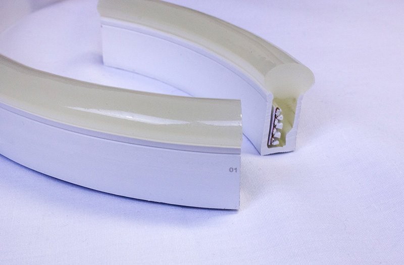
Please note: This is a horizontal bending fixture. If this were a vertical bending fixture, we would be cutting across the diffuser. The key to cutting a fixture is to ensure that you are cutting across the face of the circuit board.
What not to do
Here are some examples of how NOT to cut LED Neon Flex.
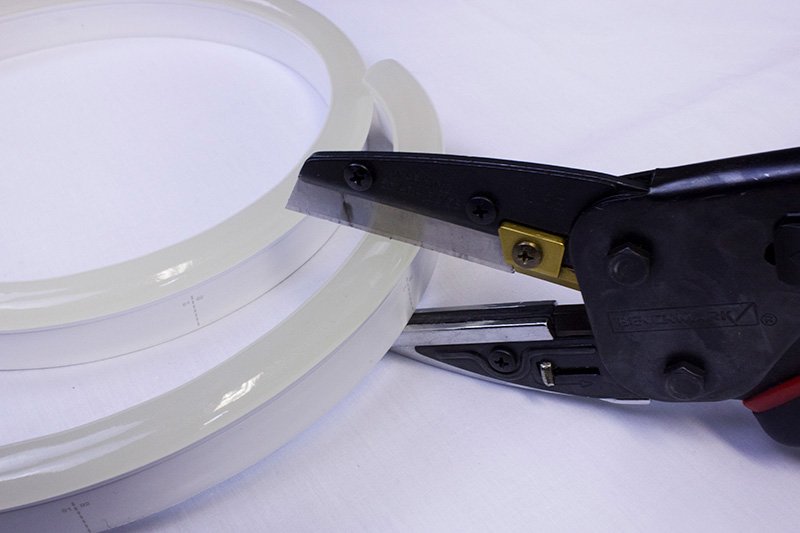
Do not cut the fixture in a way that cuts the circuit board side to side. Always cut across the face of the circuit board. For this horizontal bending fixture, this means not cutting across the top of the diffuser.
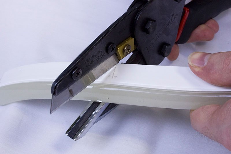
Do not cut the fixture at an angle. This will not only cause damage to the internal components, but it will also prevent your Snap Connectors from creating a proper seal with the fixture. We’re showing a dramatic example of an angled cut, but even slight angles can cause issues. Always be sure you’re going to make a straight cut before cutting through the fixture.
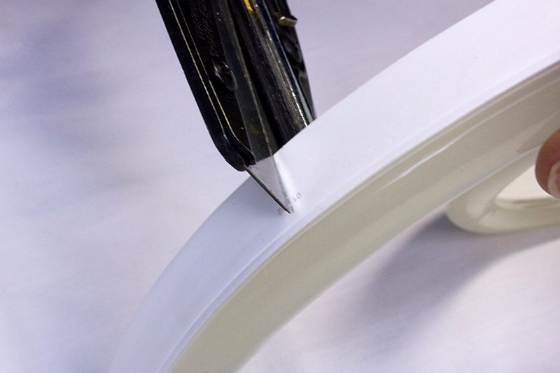
Do not make multiple cuts. This could cause jagged edges on the outer casing, and damage the internal components. When cutting LED Neon Flex it is important to make one clean cut.
Installing a Snap Connector lead
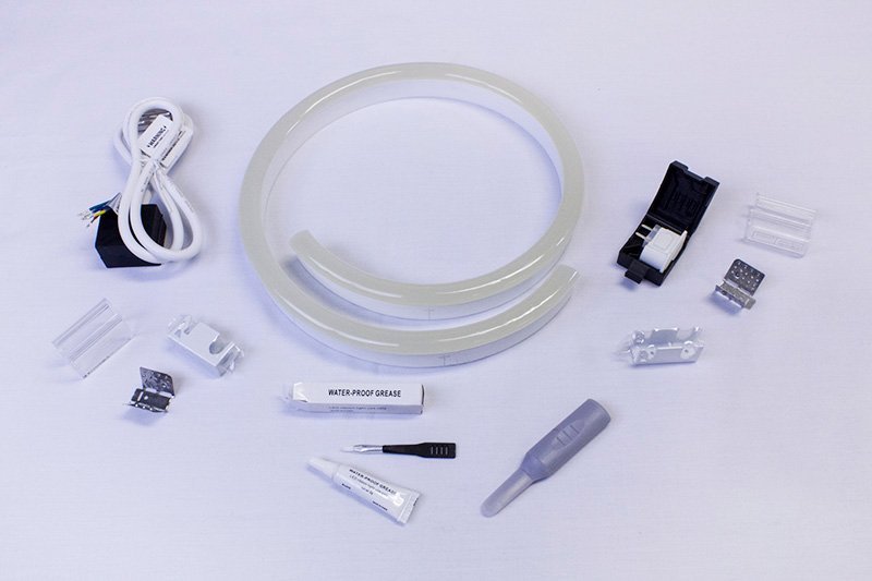
Snap Connector Lead kit shown on the left, Snap End Cap kit shown on the right
Before we begin our installation, let’s talk about the water-proof grease. This product, as well as the inducer, comes along with your Snap Connector kits. We don’t use it in today’s post because the silicone gaskets on the Snap Connectors come pre-lubricated. The grease is included in the kit in the event of the lubrication being removed from the silicone gasket during transit or handling.
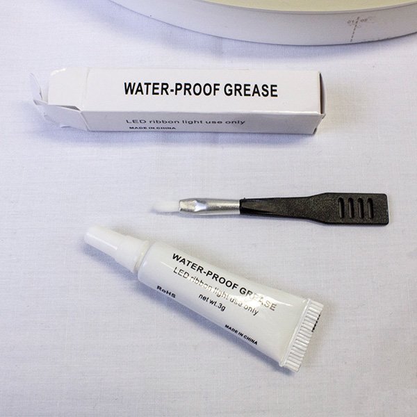
If you do need to re-apply the water-proof grease, do so using the small brush included in the box. You will want to apply the grease only to the front of the gasket where it will be pressing against the fixture.
The following steps apply to both the Snap Connector leads and end caps.
Step 1
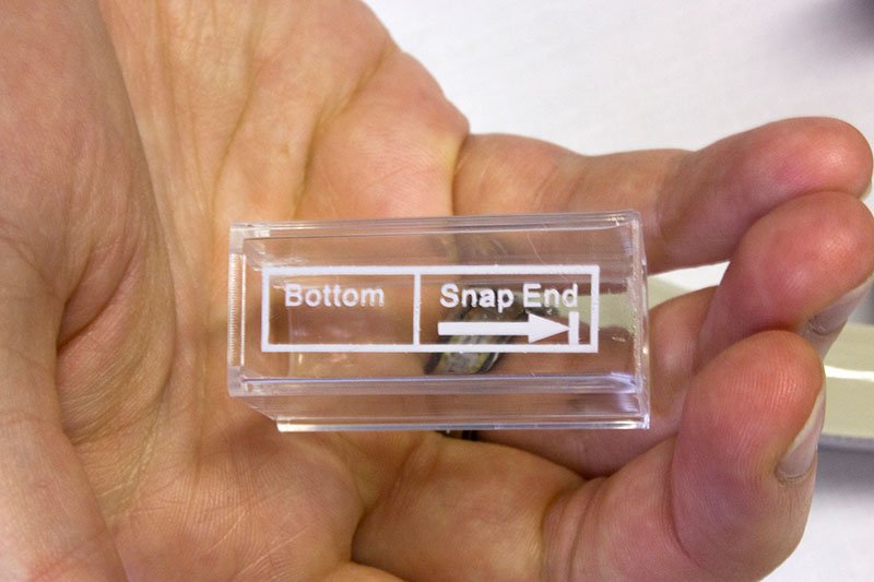
Ensure that you have the correct end and connector, as indicated by the numbers on the sides.
Step 2
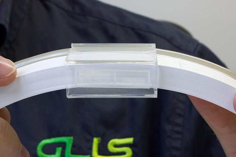
Slide the snap cover onto the fixture. Make sure the Snap End arrow is pointing towards the end of the fixture you’re installing the connector onto. Slide it back about 2 inches to give yourself enough space to finish the assembly.
Step 3
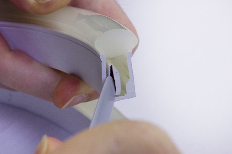
Insert the plastic inducer between the back of the PCB and the outer casing. Make sure to avoid inserting the inducer on the front side of the PCB as you could damage the LEDs.
Move the inducer up and down to create a gap that the connector pins will fit into.
Step 4
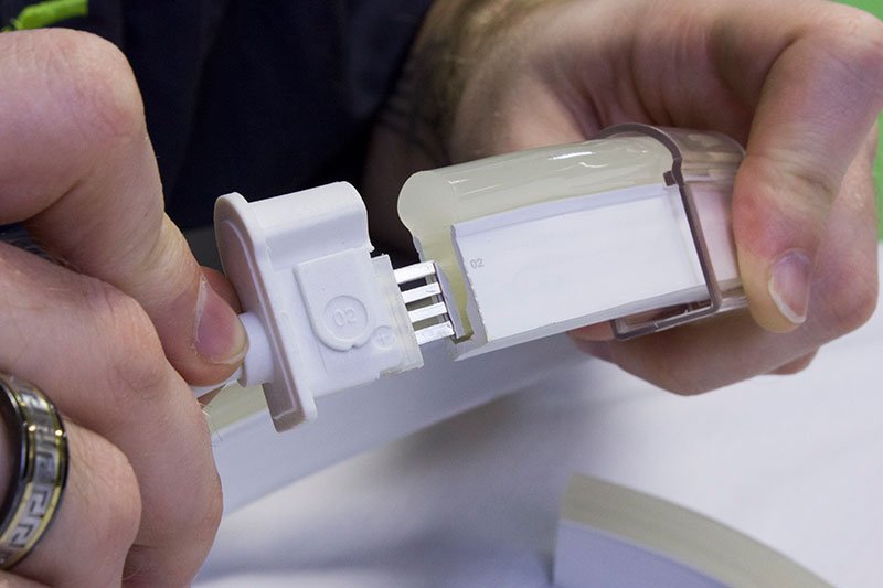
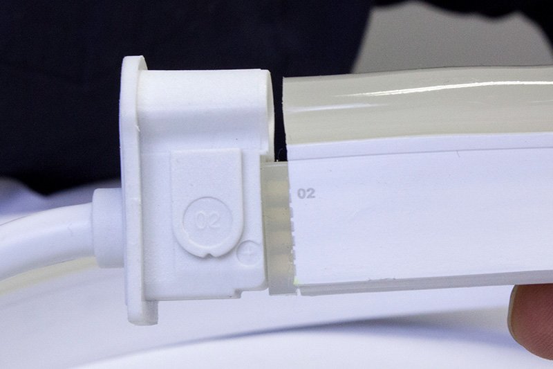
Insert the pins of the connector into the gap you created behind the PCB. Push the connector in until the silicone gasket meets the fixture.
Step 5
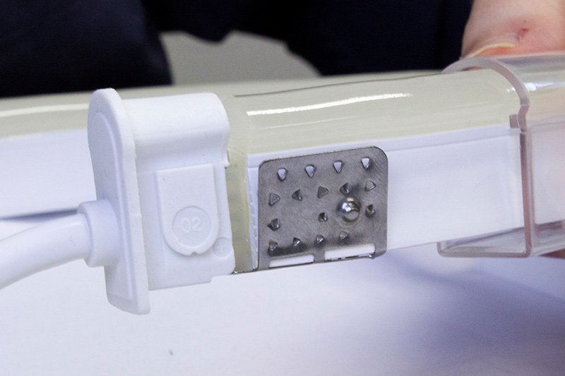
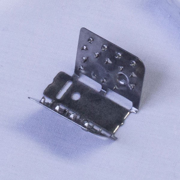
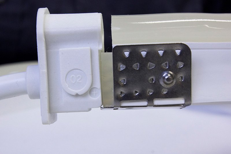
Secure the grip plate on to the end of the fixture. It is VERY important that your grip plate is flush with the cut end of the fixture in order to ensure proper compression.
Improper placement of the grip plate can cause gaps that allow dust to enter the fixture as well as water ingression.
Step 6
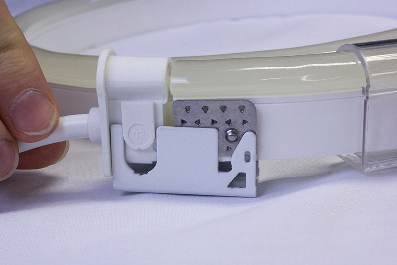
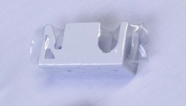
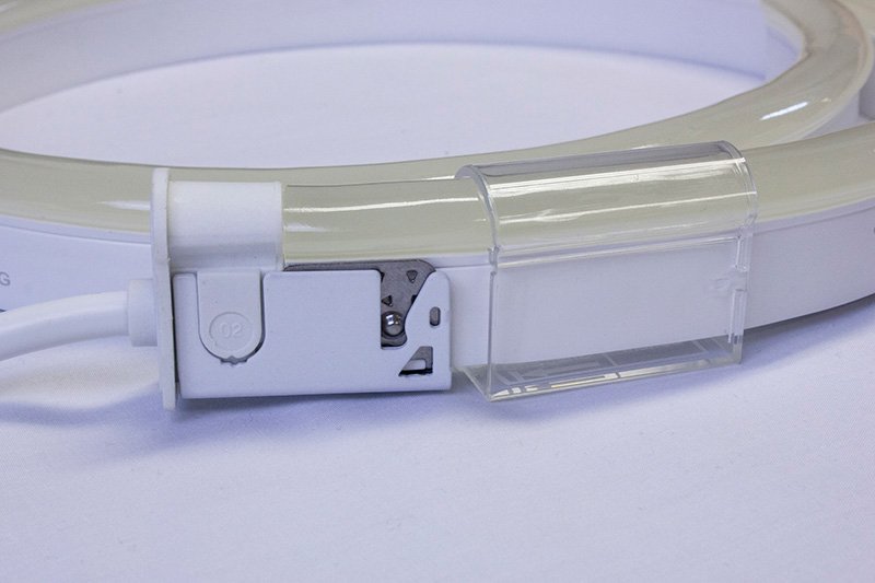
Line up the connector and grip plate with the compression clip as shown. With even pressure, push down on the top of the fixture and connector until the bottom of the fixture is flush with that of the clip.
This secures the connector to the fixture as well as forming a seal between them.
Step 7
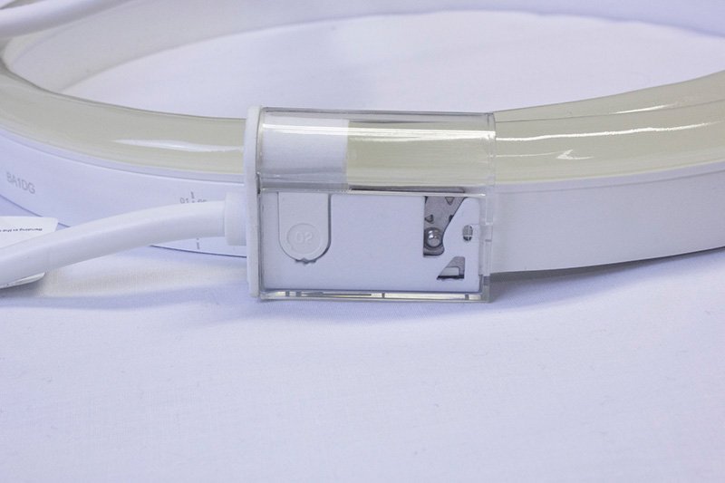
Slide the snap cover back towards the connector until it has covered the assembly and ‘snaps’ into place. You should be able to feel or hear it click into place.
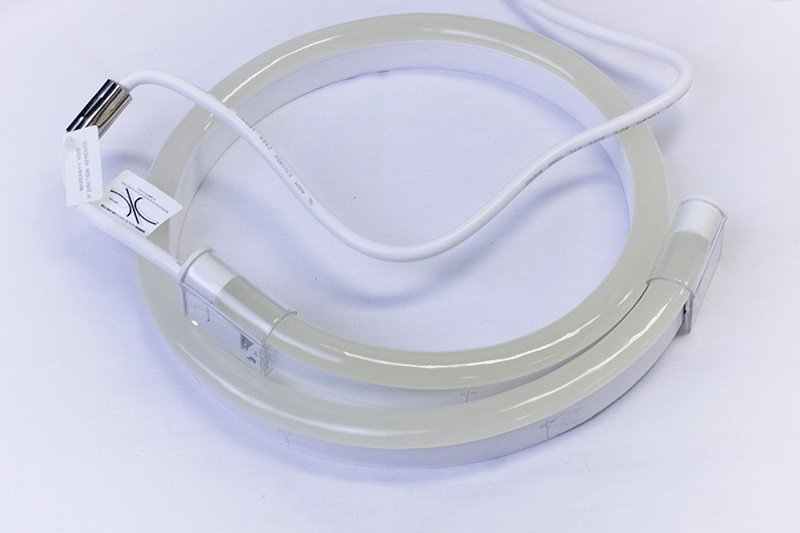
Repeat these steps with your Snap End Cap and your fixture is ready to be installed!
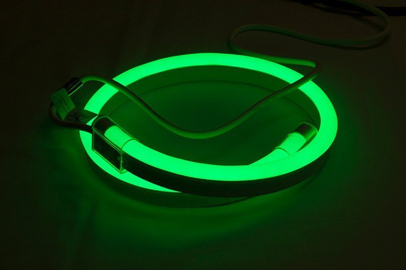
Check out our How To video below!
Check back in for our next Tech Talk; we’ll be covering the difference between a Class 2 and Class II power supply!
Have any technical questions? Contact Tech Support
Want to suggest topics for future posts? Email us!
To speak with a sales rep about our LED Neon Flex products, Contact Us today!


